Programming the STEMBoT Remote, Part 3

In part 1 and part 2 of this series, I explained how to interface the STEMBoT and its remote, from pairing to programming its buttons. In this final post, I’ll go over a complete program that gives purpose to every programmable button and both joysticks.

This program controls the onboard LED, a servo port, the motors, and the LED, SHT21, and MPU6050 plug and play modules. If you don’t have one or more of these modules, you can comment out the sections of code that use them by placing a pound sign (#) in front of the code. The LED module should be plugged into the top port, the SHT21 temperature module should be in the right port, and the MPU6050 accelerometer should be in the left port.

The joysticks are used to control each motor, and pressing the joystick buttons will change the motor speed. The directional pad (d-pad) will cause the robot to move forward or backward 1 foot, or turn 90 degrees left or right. The right and left buttons will cause the servo to move from one side to another, and the triggers will flash the LEDs on the plug-and-play module in one direction or the other. The start button prints acceleration readings to the LCD, and the back button prints temperature readings (in Fahrenheit). Finally, the colored buttons on the right will illuminate the onboard LED, and the yellow Y button will turn them all off.

To get started, download the code and drag it to the apps folder of your STEMBoT. After resetting your bot, it should appear in the list of apps on the main menu. Be ready to pair your remote once you open the app! After pairing, the program is ready to go and you can try out all of the buttons on your remote.

The code itself starts by importing the required modules. The standard “async def main():” header defines the start of the program. The first two lines are ones we’ve seen in part 1 of this series: they create Remote() and RemoteData() objects for interacting with the controller. The next line sets up a Servo() object as s1 (this will be the servo port closest to the top of the board). The first major block of code sets up the motors and functions for controlling them. The motorWake() and motorSleep() functions enable and disable the motors. The motorStop() function combined with the brake_mode setting will cause the motors to stop in place. Otherwise, the wheels will keep spinning on their own inertia. The remaining four functions are used for d-pad movement, and will put the motors to sleep once complete, which helps to save power.

The next block of code contains a function that cycles through the LEDs in the top port. It starts by turning them all off, then turns on one according to the number in ledNum, which is then increased or decreased by 1, depending on the direction passed to the function (either “CW” for clockwise or “CCW” for counterclockwise). This function was written with the circular LED module in mind, but it will work with the rectangular module.

The following blocks of code access the accelerometer and temperature sensor modules, and will print the results to the LCD (black text on a white background). If you want to switch the modules around, “left” and “right” can be changed.

Once the program is selected from the main menu, the pairing code starts. Just like in part 1, the r.pair() method is called to get the controller and the STEMBoT talking to each other. The surrounding code is used for feedback, so you know whether or not the pairing was successful (using the r.is_paired() method).

The final block of code starts with a while(1) statement, so everything that comes after occurs in an infinite loop. The code will try to read the remote’s signal, and if that fails, the motors will turn off. That way, if you drive the STEMBoT outside of signal range, it won’t drive itself off a cliff! The try…except block of code is a form of error handling, which is a vital part of complex software.

Just like in part 2, this code will test if the colored buttons are being pressed, and will turn on the onboard LED corresponding to the button. If the yellow Y button is pressed, a short for loop is executed to shut them off (because there’s no yellow LED!).

Next, the LB and RB buttons are tested, and will turn the servo from one angle to another. The triggers will illuminate the LED plug-and-play module in one direction or the other by using the function described earlier.

Pressing the start button will print acceleration data, and pressing the back button prints temperature data. This section of code is done with an if..elif statement to give acceleration data priority if both buttons are pressed (if the start button is pressed, the elif section will not execute). If you wanted to give the temperature data priority, you could replace the elif with if. Then, if both buttons are pressed, the graphics.paint() function in the second if statement will overwrite the acceleration data.

The next block of code changes the speed variable either higher or lower depending on which joystick button is pressed. Pressing the left joystick button decreases the speed and the right joystick increases it. This happens in increments of 100, and will limit the speed between 100 and 400, giving 4 speeds. A delay of almost half a second is included in these statements to prevent accidentally registering multiple button presses (this delay is the same amount of time the main menu uses!).

The final block of code will drive the motors based on the joysticks, similar to the two-joystick driving mode offered in the basic code. The big difference is that the speed isn’t based on how far you push the joysticks, it’s fixed based on the speed variable which can be changed by clicking the joysticks.

This program was written to demonstrate the power that users have over the controller, and is easily modifiable to suit your needs. I hope that this series gives you the knowledge and confidence to start writing your own wireless controller programs!

Programming the STEMBoT Remote, Part 2

In the previous post, I explained how to access the pairing and reading functions of the remote controller, as well as how to read joystick values. This post will explain how to access the buttons on the remote and how to use this data to control the STEMBoT’s LED. We’ll assume the remote module has been imported already and that the Remote() and RemoteData() classes have been instantiated.

As detailed in the previous post, once the remote and the SB2 are paired, the remote (while on) will continuously send signals to the SB2 to indicate the remote’s most recent button and joystick states. Capturing these signals is done with the read() method, and the data is stored in the RemoteData() class (or rather, the variable to which this class has been assigned, rdata). Getting the joystick values is done by appending the rdata variable with a period and the name of the joystick value, as indicated in the User’s Manual. Getting the button data is a bit trickier, and uses a process called masking. (If you’re already familiar with the concept, or just want to dive into programming the remote, skip to the paragraph starting with the remote).

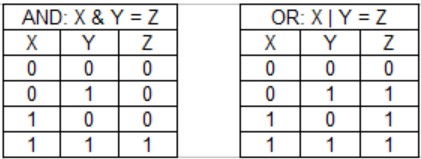
Masking is a process that allows a programmer to set bits in a stream of data to either 1 or 0. This is done using bitwise operators. Operators most people are familiar with include mathematical operators, such as plus (+) and minus (-) signs. Bitwise operators perform operations on individual bits, and include AND (&) and OR (|) signs. These operators will produce an output depending on the inputs and the truth table associated with the operator. For example, the following truth tables define the output (Z) of an operator on two inputs (X and Y):

You can see that in the case of the AND operation, the output Z will be 1 if and only if both X and Y are 1. For the OR operation, the output Z will be 1 if X or Y (or both) are 1.

Let’s say we wanted to change one variable from 0b1111 to 0b1000 (the 0b prefix tells Python that the value is in binary, so really it’s 1111 and 1000). The code would look like this:

>>>binaryvalue=0b1111
>>>binaryvalue = binaryvalue & 0b1000
>>>bin(binaryvalue)
‘0b1000’

The first line defines the variable. The second reassigns it to the original value AND-ed with the desired value. The third line returns the value (the bin() function is used to return the value in binary, otherwise it will return a decimal value).

One might think that this isn’t very useful: after all, you could just reassign the original variable with the new value and skip the bitwise operation altogether. Instead of using bin(), try using bool() and examine the result:

>>>bool(binaryvalue)
True

Boolean values are either True or False; if the object in question is 0, its Boolean value is False. If the object is anything other than 0, its Boolean value is True. This is where these bitwise operators come in handy: they can tell us whether or not a specific bit is a one or a zero. In the above case, we’re being told that the third bit (closest to the ‘b’) is a one. Try the above code again, except this time set binaryvalue equal to 0b0111. The end result will be False because that bit closest to the ‘b’ is a 0, and so the result of the bitwise operation is 0b0000. In terms of the truth tables above, ‘binaryvalue’ is our X and ‘0b1000’ is our Y.

The remote sends its button states as a sixteen-bit value (actually 17, but the first bit is always 1) where each bit represents a button. If a button is pressed, that bit is set to 1, otherwise it remains 0. Fetch the button data by using the remote’s read() method. The data is stored in the ‘buttons’ variable, and its raw binary value can be read with the bin() function, like so:

>>>r.read(rdata)
>>>bin(rdata.buttons)
‘-0b10000000000000000’

Since none of the buttons were being pressed, each of the relevant bits are set to zero. Now, hold down the green A button and capture the signal with the read() method.

>>>r.read(rdata)
>>>bin(rdata.buttons)
‘-0b11000000000000000’

The 16th bit has been set to 1 by pressing the green button. If we want to know that this has been set to 1 without visually examining it each time, we can perform an AND operation with the known value for the green button, which can be found in section 4.4.2.2 of the User’s Manual.

>>>bool(rdata.buttons & remote.A_BUTTON)
True

If you print out the value of remote.A_BUTTON in binary, you’ll see that there’s a single bit (out of 16) set to one, in the same place as the rdata.buttons value. AND-ing these ones results in a one according to the truth table above, which is a True Boolean value. The following code uses masking to test the state of the X, A, and B buttons and changes the color of the LED accordingly:

>>>import pyb
>>>red=pyb.LED(1)
>>>grn=pyb.LED(2)
>>>blu=pyb.LED(3)
>>>def allOff():
. . .     red.off()
. . .     grn.off()
. . .     blu.off()
. . .
>>>X = remote.X_BUTTON
>>>Y = remote.Y_BUTTON
>>>A = remote.A_BUTTON
>>>B = remote.B_BUTTON
>>>while(1):
. . .     r.read(rdata)
. . .     if rdata.buttons & X:
. . .         blu.on()
. . .     if rdata.buttons & A:
. . .         grn.on()
. . .     if rdata.buttons & B:
. . .         red.on()
. . .     if rdata.buttons & Y:
. . .         allOff()
. . .

The first part of the code sets up the LEDs and builds a function called allOff() to turn them all off. The next part assigns each of the button values to a one character variable (which is not necessary, but it’s done to make writing the main function easier). The while(1) loop continuously reads the remote data and turns on or off the LED, depending on which button is pressed. In most applications involving the remote, continuously reading the data is more useful than a one-shot operation, and a while(1) loop is a way to do this.

In the next post, I’ll provide and explain a complete example program that uses each button and joystick on the remote.

Programming the STEMBoT Remote, Part 1

If you’re familiar with the CEENBoT, then you’ve probably used its remote controller. The PS2-like controller comes with a detachable receiver and allows users to drive the robot, change speeds, and change modes.

Early on in the development phase of the STEMBoT, it was decided that the radio system needed to be developed to give users more control over its buttons. This resulted in the new controller system, which uses an Xbox controller case and custom hardware that allows users to program (in Python) nearly every button and the joysticks. In this post, I’ll explain the basics of programming the remote, as well as how to get joystick values. The following post will demonstrate how to get button values and use them to control the SB2 LED. The final post will go through the process of writing a complete program for the remote controller that lets you get the most from the new radio system.

To begin, make sure your remote has charged batteries, and that your STEMBoT is plugged in to your computer and the REPL is running. To use the remote system, we’ll import the remote module.

>>>import remote

There are two major objects that we’ll need to create to program using the remote: the Remote() object which allows us to access various functions, and a RemoteData() object which will let us store and organize the remote controller signals. We’ll instantiate (or create an instance of) each object by assigning them to variables. For simplicity’s sake, we’ll call these new objects ‘r’ and ‘rdata’.

>>>r=remote.Remote()
>>>rdata=remote.RemoteData()

The next step is to make sure the remote and STEMBoT are talking to each other. To do this, we must use the pair() method within the Remote() class. In the case of the STEMBoT and its remote, pairing is a five-step “handshaking” process that allows the STEMBoT and the remote to agree to a set of rules. So long as the rules are observed (which is done automatically) the STEMBoT knows exactly which controller is trying to talk to it. As soon as the code to begin pairing is sent, press the pairing button next to the left button (LB) at the top of the controller. If the pairing was successful, the REPL will return 2. If pairing is unsuccessful, you may need to reset the STEMBoT and try again. However, once a STEMBoT and remote is paired, both devices will remember one another, so this only needs to be done once.

>>>r.pair()
2
>>>

Now that the devices are paired, we can send (transmit) data from the remote and capture (receive) it on the robot. The remote sends data constantly and automatically as long as it’s on, so we need to capture and read what was sent. To do this, use the read() method of the Remote() class. This method accepts two parameters: the variable where the data will be stored (rdata, in our case), and how long it should try to read the data, called the timeout. The timeout is set to 2 seconds by default, and probably doesn’t need to be changed. We want to store the data in the rdata variable that we created previously, so the function will look like this:

>>>r.read(rdata)

As soon as you send that line of code, the STEMBoT will capture the most recent data sent by the remote. Now we have to analyze the data to put it to use. The RemoteData() class contains 5 variables, 4 are reserved for joystick directions, and one is for the sixteen programmable buttons. Let’s take a look at the joysticks first. Type in the following line (if the remote shuts off while programming, just turn it back on and it should still be paired and ready to go):

>>>rdata.ljoy_up_down
0
>>>

This line reads the up/down value from the left joystick. The other values are ljoy_left_right, rjoy_up_down, and rjoy_left_right. The code will return 0 unless the joystick was being pressed or the remote needs calibration. Try holding the left joystick up all the way, then capture the remote data again with r.read(rdata) and read the joystick value with rdata.ljoy_up_down. It should return 128, which is the maximum value for upward deflection on the this joystick. The maximum value in the opposite direction is -127. The complete list of joystick values can be found in section 4.4.2.1 of the User’s Manual.

The next article in this series will explore the programmable buttons and will include a sample program to change the color of the LED using the controller.

Coming Soon to SBI!

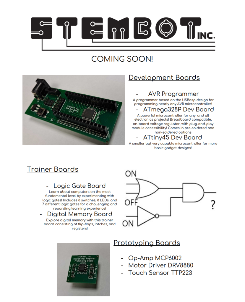
Later this year, SBI will be introducing a new line of prototyping and development supplies! This line will feature breadboard-compatible AVR development boards, using the same type of microcontroller as Arduino and the original CEENBoT. It will also include trainer boards for digital logic, memory, and combinational circuits, to give learners a hands-on experience with the building blocks of modern computers!

We will also soon be releasing several more plug-and-play modules, including IR distance, ultrasonic distance, and the ESP32 WiFi/Bluetooth module for remote programming. In addition to the boards developed in-house, SBI will start making prototyping and development supplies such as breadboards, multimeters, and passive components available for purchase in our shop!

Measuring Solar Power with STEMBoT

To maximize the efficiency of solar panels, pyranometers are used to measure solar irradiance under a variety of conditions. Solar irradiance is a measure of power per square meter, and depends on factors like the time of day and the direction of a solar panel. As with any energy source, efficiency is an important consideration since it allows us to do more with less. This project uses a solar cell, a simple amplifier circuit, a voltmeter, and the STEMBoT to measure the power output of the solar cell, which is then used to calculate irradiance.

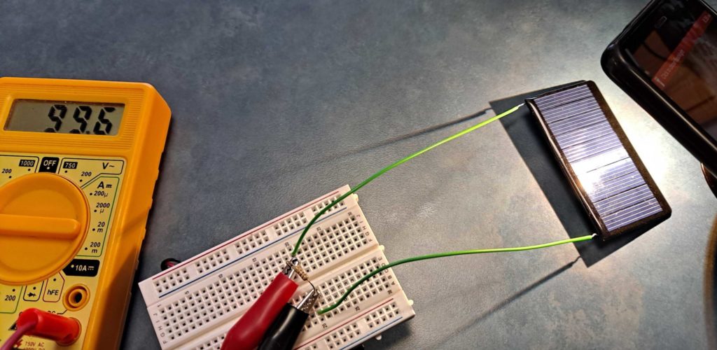
To begin, the maximum voltage of the solar cell with a load (resistor) attached should be tested and recorded. This will be helpful in designing the amplifier circuit, since the output of the circuit cannot exceed the input of the STEMBoT’s analog-to-digital converter (ADC). To measure the maximum voltage, I selected a resistor of 100 Ohms and placed it in series with the solar cell. Then, while flashing the brightest flashlight I could find directly over the cell, I took voltage readings.

I had to move the flashlight around a bit to get a maximum reading of around 100mV.

With a maximum voltage of (roughly) 100mV and a maximum input to the ADC of 3.3V, I know through simple division that the amplifier’s gain should be no more than 33. [The gain of a DC voltage is just the output divided by the input]

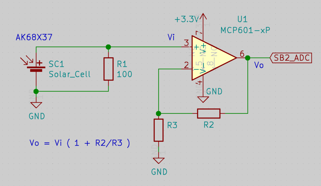
The next step is to design the amplifier circuit with this gain in mind. For this, an operational amplifier (op-amp) can be used with a basic non-inverting amplifier circuit. I chose an MCP-601 for the op-amp since it can be used with the 3.3V supply the STEMBoT offers. The non-inverting amplifier configuration requires two resistors to define the gain according to the equation in the following schematic.

Resistors R2 and R3 define the gain. Resistor R1 is the load, and the output of the op-amp goes to the STEMBoT ADC.

I used a 2.2kOhm resistor for R2 and an 82 Ohm resistor for R3 for a gain of about 27.8. While not ideal, the most important thing is that the gain doesn’t exceed 33 for this setup. It’s okay if the maximum output of the op-amp is below 3.3V, but it cannot be above.

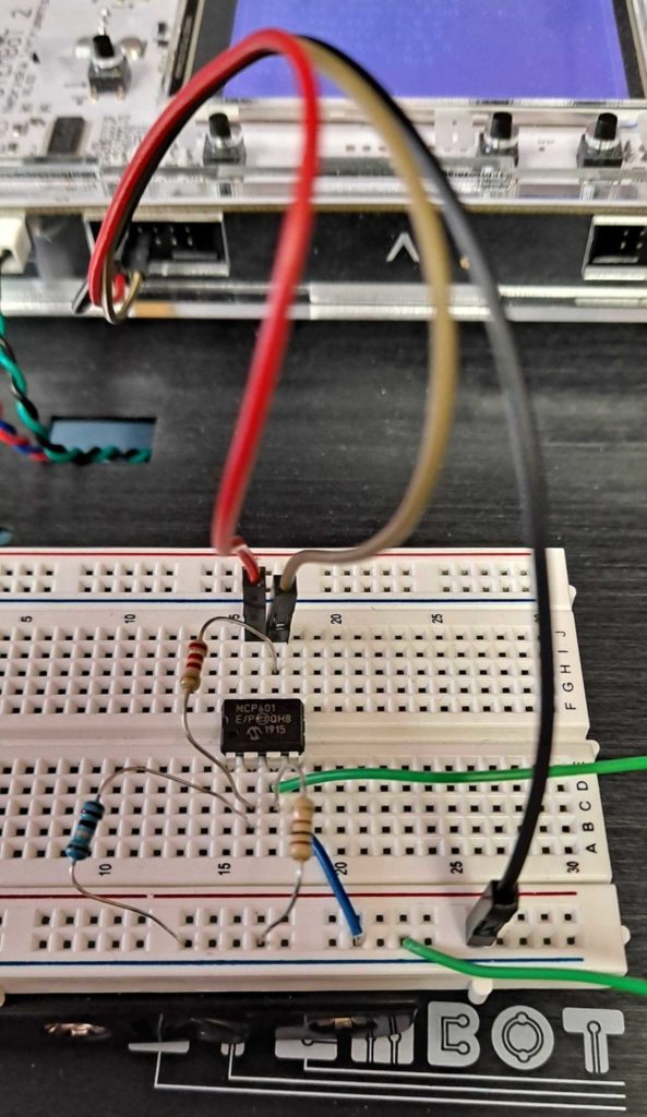
If you’re using a different op-amp, you should consult the respective datasheet to determine how the pins are configured, but in the end this is what my pyranometer looks like.

The brown wire is the output of the op-amp, and is connected next to the 3.3V output of the STEMBoT. The green wires lead to the solar cell.

The reading on the ADC will give a number between 0 and 65536 or 2^16. This reading represents a fraction of the maximum voltage (3.3V). For instance, a reading of 0 will indicate 0V on the ADC, and a reading of 65536 would indicate 3.3V. A reading of 32768 is halfway between 0 and 65536, and would represent 1.65V, or halfway between 0V and 3.3V. To find the voltage on the pin based on other readings, take the reading divided by the maximum on the ADC, and multiply it by 3.3V.

ADC_reading/ADC_max = V_reading/V_max
so, V_max * ADC_reading/ADC_max = V_reading

That reading will have to be divided by the gain to get the voltage out of the solar cell.

To find the power based on the voltages, well have to use Ohms Law, V=IR, where V is the voltage, I is the current, and R is the resistance. First find the current going though the load resistor by dividing V by R. Then to find power, multiply V and I. To find irradiance, divide this power by the surface area of the solar cell. In this example, I’m using a 68mm x 37mm cell. The total surface area is then 0.002516m^2. Calculating these values using Python should look something like this:

>>>import machine
>>>import utime
>>>ADC=machine.ADC(“C4”)
>>>ADC_max=2**16
>>>V_max=3.3
>>>gain=27.8
>>>R=100
>>>surface_area=0.002516
>>>while(True):
. . . utime.sleep_ms(500)
. . . ADC_reading = adc.read_u16()
. . . V = V_max * ADC_reading/ADC_max / gain
. . . I = V / R
. . . P = I * V
. . . irradiance = P / surface_area
. . . print(str(irradiance))

This code will print out the solar irradiance every half second. Chances are unless you’re programming in a very bright room, the value returned will be very small. If you shine a light directly over the cell, the irradiance will increase, and if you move your hand over the cell it should fall to zero.

While you won’t be able to power your STEMBoT with solar power directly (yet!) this is still a useful tool for figuring out where you should point any solar panels for making the most of them.

STEMBoT and Arduino

When I first started getting into electronics and programming, Arduino was the best way to start learning. Of course, there was no STEMBoT back then. In fact, I still have a number of programs and schematics for projects that I finished long ago.

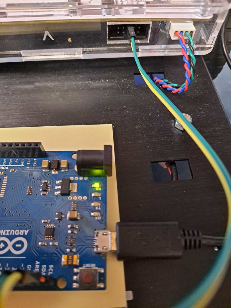
One of the best features of the STEMBoT is its UEXT headers for plug and play modules. These headers are not limited to the modules created by SBI, and can be used to interface with any number of embedded systems, such as Raspberry Pi, Micro-bits, and Arduino. For this project, I’ve connected an Arduino to my STEMBoT through the two-wire interface.

At a minimum, you’ll need a STEMBoT, an Arduino of your choice, two wires, and the Arduino IDE installed on your computer. Plug in your Arduino and upload the “slave_sender” program found under File->Examples->Wire. This will set up the Arduino to respond to requests by the “master” which in this case is the STEMBoT. The Arduino is given an address of 8 (this can be changed in the line of code Wire.begin(8); ). When responding to requests the Arduino will return up to 6 bytes (seen in the line Wire.write(“hello “); ).

Connect the two devices by attaching one wire from SCL pin on your Arduino (it should be marked on the board itself) to the center pin of one of the plug-and-play headers, next to the cut-out part of the header’s plastic. [This cut-out is called the “key” and it’s there to make sure your plug-and-play modules aren’t plugged in the wrong way!] Then attach the second wire from the Arduino’s SDA pin to the plug-and-play header pin next to the first pin.

Be sure your Arduino isn’t resting directly on the STEMBoT’s metal chassis, as it will cause your Arduino to short out! I’m using some post-it notes to create a barrier, but any non-conductive surface is fine.

Once that’s set up, make sure your STEMBoT is plugged in and fire up PuTTY. Type in the following lines of code:
import machine
i2c=machine.I2C(1,freq=9600)
This will create a serial communication object (i2c) on bus 1 (the left and right plug-and-play headers) with a bit rate of 9600 (higher speeds work too, but this one is very common and works with nearly all serial communication devices).

Next, type in:
i2c.scan()
This will scan the bus for all connected devices. Since the Arduino has an address of 8, PuTTY will print out [8] once the scan is complete. If you have more devices connected, there would be more results, but at a minimum the Arduino’s address should be returned. If not, make sure your connections are correct.

Finally, input:
i2c.readfrom(8,6)
This line will read 6 bytes of information from address 8. If all goes well, PuTTY will print the line b’hello ‘, which is the bytes-formatted data which was sent from the Arduino. If you wanted to read only the ‘hello’, you could type in i2c.readfrom(8,5) and it would omit that final space.

To turn the bytes object into a string, save the data and append it with the .decode() method, like so:
info=i2c.readfrom(8,6)
info.decode()

The example code provided by Nicholas Zambetti in the Arduino IDE can be easily modified to change the address and the text that’s sent, and can be copied over into existing projects to get the best of both worlds, Arduino and STEMBoT!

STEMBoT’s Balancing Act

Robotic autonomy is the ability of some robots to act without human intervention. Though it may have once sounded like something from science fiction, autonomous robots are becoming increasingly common in our daily lives. Many of these robots have been designed to perform menial or dangerous tasks, and can be seen in hospitals, restaurants, and war zones. With the right sensors and a bit of programming, the STEMBoT can gain a level of autonomy!

The STEMBoT shown here balances with the use of the MPU6050 Plug and Play module and the sample code found here.

Digging into the code, there are several functions that have to do with the MPU6050 and the motors. The first two functions, offsetAccel and offsetGyro, take a number of data samples to establish a baseline for more accurate measurements. Since no sensor is perfect, finding out how imperfect your sensor is allows you to compensate and get more accurate data. While this calibration isn’t strictly required, it can be helpful especially if your MPU6050 is giving off weird readings.

The next set of functions are used to control the motors. They’re all basic and portable, which means you can copy and paste them into your own code! Just make sure you use them in the right order (motors need to be woken up [motorsWake()] before use).

The main function gets the MPU6050 module and LCD ready (lines 85- 88), initializes the motors (lines 90 and 91), and uses the averaging functions to generate offset values (lines 96 and 97). The infinite loop, starting at while(1), gets the readings (including temperature!) and then applies the offset by subtracting the averaged calibration values from the new readings. The data is then printed to the LCD for convenience (lines 116 – 121).

Lines 122 – 131 is where the magic happens. The MPU6050 will naturally read the acceleration due to gravity. When the SB2 is motionless on a level surface this value will be around 9.8m/s^2 along a single axis, the one going up and down (the y axis if your module is plugged into the top port). The readings along the other axes should ideally be zero, but in practice will hover around zero. When the SB2 is thrown off balance, the acceleration due to gravity will be felt along other axes. These lines of code test the acceleration felt along the z-axis (along the length of the SB2) and if that acceleration exceeds 1 m/s^2 (in either direction, + or -), the SB2 “knows” that the center of the lever hasn’t been found, and will activate the motors to move in that direction. Because this happens in an infinite loop, the SB2 will continue moving back and forth until the sweet spot is found, where the acceleration along the z-axis is close to zero. It will then stop and put the motors to sleep. The delay (await) after these lines of code makes the SB2 move for half a second before retesting the acceleration data.

The algorithm (those magic lines of code and the logic behind them) that gives the SB2 autonomy in this example is, well, crude. It gets the job done, but it’s not very efficient. The reason behind this is to demonstrate that it doesn’t require much in the way of programming to achieve some level of autonomy. It takes only a few lines of code make the SB2 think and behave on its own! With how easy it is to give this robot intelligence, it’s only a matter of time before some mad programmer starts taking over the world with STEMBoTs!


Module used: MPU6050

Program used: Balancing_Act.py

Keeping Warm with STEMBoT!

With frigid temperatures outside, it’s important to bundle up and help reduce your impact on the power grid with the following tips:

Lower your thermostat a few degrees and keep warm with sweaters or blankets

Avoid using your washer/dryer or dishwasher during the coldest parts of the day (late night and early morning)

Seal windows and doors with weather stipping

Avoid phantom power loss by unplugging electronic devices when not in use

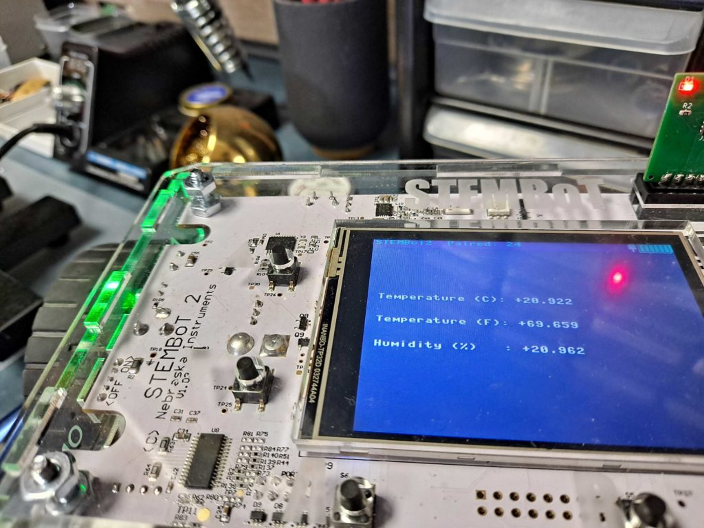
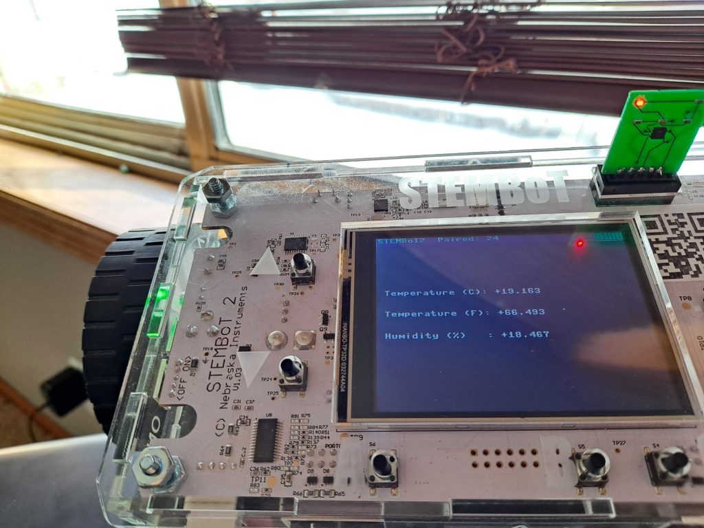
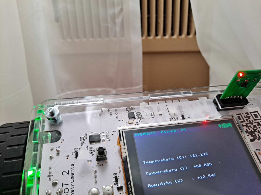
I took my STEMBoT around to see where I could improve insulation throughout my home:

It’s reasonably comfortable in my home office

The area near my basement windows definitely needs improvement

Of course it’s warmest right next to the heating/cooling vent. That must be why my cat loves hanging out there!

Program used: DEMO_PnP_SHT21

PnP Module Used: SHT21 Temperature/Humidity Sensor

New Programming Guides

In anticipation of this year’s Nebraska Robotics Expo, SBI has started working on a series of YouTube videos that explain how to program the STEMBoT. The series will start with the most basic programming features and will work through use of the Plug and Play modules as well as fun applications of the same!

The User’s Manual has been updated to reflect the most current API. In addition, a quick programming reference has been developed and can be found here. The new guide goes over each of the STEMBoT capabilities at a high level for easy use.

Mobile Programming Application!

Along with the STEMBoT 2 launch, we hope to deploy a functional version of our drag and drop mobile programming application before the end of the year. 

The STEMBoT Mobile app will enable students and teachers to use drag and drop programming to design their programs that they can wirelessly upload to their STEMBoT 2. 

Likewise, teachers will be able to use the mobile application to share specific programs to go along with their lessons. We are very excited about the potential this app has for greatly improving virtual-learning and at-school learning. It will make lesson setup so much faster and simpler for organizations and their educators! 

In addition, with support from the University of Nebraska’s computer science department capstone team, the mobile application will also have a Simulation component that allows students without a STEMBoT to simulate their code in a really cool 3d environment. Students will get to gain hands-on critical thinking and programming experience, even without a robot! 

On another note, our two engineering interns are learning all about advanced power supply concepts and electronics engineering!