Measuring Solar Power with STEMBoT

To maximize the efficiency of solar panels, pyranometers are used to measure solar irradiance under a variety of conditions. Solar irradiance is a measure of power per square meter, and depends on factors like the time of day and the direction of a solar panel. As with any energy source, efficiency is an important consideration since it allows us to do more with less. This project uses a solar cell, a simple amplifier circuit, a voltmeter, and the STEMBoT to measure the power output of the solar cell, which is then used to calculate irradiance.

To begin, the maximum voltage of the solar cell with a load (resistor) attached should be tested and recorded. This will be helpful in designing the amplifier circuit, since the output of the circuit cannot exceed the input of the STEMBoT’s analog-to-digital converter (ADC). To measure the maximum voltage, I selected a resistor of 100 Ohms and placed it in series with the solar cell. Then, while flashing the brightest flashlight I could find directly over the cell, I took voltage readings.
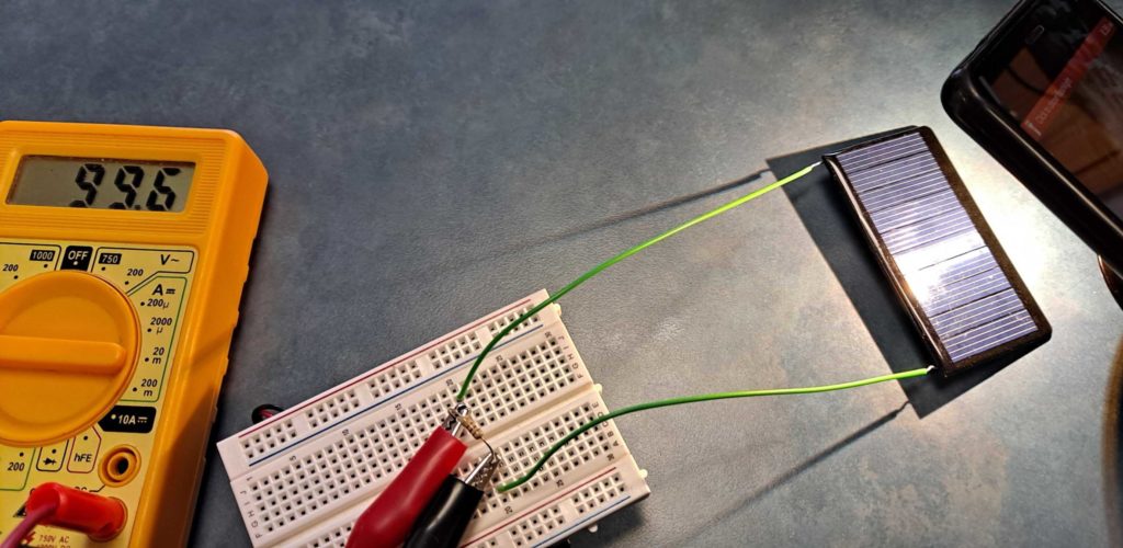
I had to move the flashlight around a bit to get a maximum reading of around 100mV.

With a maximum voltage of (roughly) 100mV and a maximum input to the ADC of 3.3V, I know through simple division that the amplifier’s gain should be no more than 33. [The gain of a DC voltage is just the output divided by the input]

The next step is to design the amplifier circuit with this gain in mind. For this, an operational amplifier (op-amp) can be used with a basic non-inverting amplifier circuit. I chose an MCP-601 for the op-amp since it can be used with the 3.3V supply the STEMBoT offers. The non-inverting amplifier configuration requires two resistors to define the gain according to the equation in the following schematic.
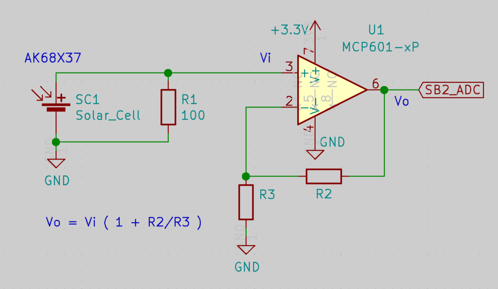
Resistors R2 and R3 define the gain. Resistor R1 is the load, and the output of the op-amp goes to the STEMBoT ADC.

I used a 2.2kOhm resistor for R2 and an 82 Ohm resistor for R3 for a gain of about 27.8. While not ideal, the most important thing is that the gain doesn’t exceed 33 for this setup. It’s okay if the maximum output of the op-amp is below 3.3V, but it cannot be above.

If you’re using a different op-amp, you should consult the respective datasheet to determine how the pins are configured, but in the end this is what my pyranometer looks like.
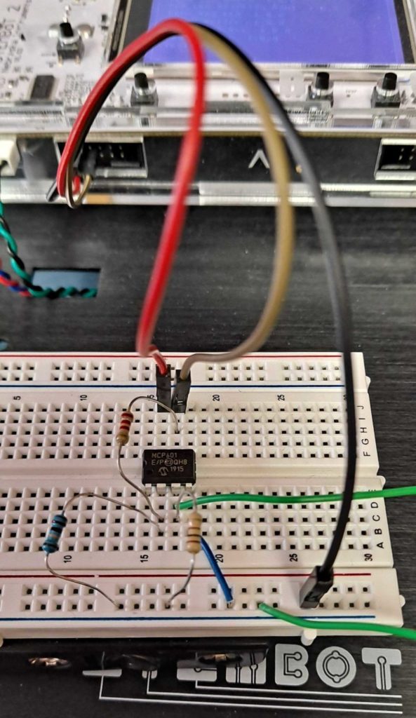
The brown wire is the output of the op-amp, and is connected next to the 3.3V output of the STEMBoT. The green wires lead to the solar cell.

The reading on the ADC will give a number between 0 and 65536 or 2^16. This reading represents a fraction of the maximum voltage (3.3V). For instance, a reading of 0 will indicate 0V on the ADC, and a reading of 65536 would indicate 3.3V. A reading of 32768 is halfway between 0 and 65536, and would represent 1.65V, or halfway between 0V and 3.3V. To find the voltage on the pin based on other readings, take the reading divided by the maximum on the ADC, and multiply it by 3.3V.

ADC_reading/ADC_max = V_reading/V_max
so, V_max * ADC_reading/ADC_max = V_reading

That reading will have to be divided by the gain to get the voltage out of the solar cell.

To find the power based on the voltages, well have to use Ohms Law, V=IR, where V is the voltage, I is the current, and R is the resistance. First find the current going though the load resistor by dividing V by R. Then to find power, multiply V and I. To find irradiance, divide this power by the surface area of the solar cell. In this example, I’m using a 68mm x 37mm cell. The total surface area is then 0.002516m^2. Calculating these values using Python should look something like this:

>>>import machine
>>>import utime
>>>ADC=machine.ADC(“C4”)
>>>ADC_max=2**16
>>>V_max=3.3
>>>gain=27.8
>>>R=100
>>>surface_area=0.002516
>>>while(True):
. . . utime.sleep_ms(500)
. . . ADC_reading = adc.read_u16()
. . . V = V_max * ADC_reading/ADC_max / gain
. . . I = V / R
. . . P = I * V
. . . irradiance = P / surface_area
. . . print(str(irradiance))

This code will print out the solar irradiance every half second. Chances are unless you’re programming in a very bright room, the value returned will be very small. If you shine a light directly over the cell, the irradiance will increase, and if you move your hand over the cell it should fall to zero.

While you won’t be able to power your STEMBoT with solar power directly (yet!) this is still a useful tool for figuring out where you should point any solar panels for making the most of them.
STEMBoT and Arduino

When I first started getting into electronics and programming, Arduino was the best way to start learning. Of course, there was no STEMBoT back then. In fact, I still have a number of programs and schematics for projects that I finished long ago.

One of the best features of the STEMBoT is its UEXT headers for plug and play modules. These headers are not limited to the modules created by SBI, and can be used to interface with any number of embedded systems, such as Raspberry Pi, Micro-bits, and Arduino. For this project, I’ve connected an Arduino to my STEMBoT through the two-wire interface.

At a minimum, you’ll need a STEMBoT, an Arduino of your choice, two wires, and the Arduino IDE installed on your computer. Plug in your Arduino and upload the “slave_sender” program found under File->Examples->Wire. This will set up the Arduino to respond to requests by the “master” which in this case is the STEMBoT. The Arduino is given an address of 8 (this can be changed in the line of code Wire.begin(8); ). When responding to requests the Arduino will return up to 6 bytes (seen in the line Wire.write(“hello “); ).

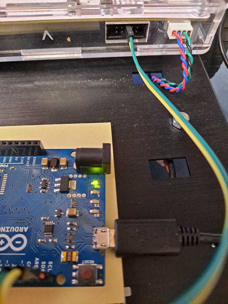
Connect the two devices by attaching one wire from SCL pin on your Arduino (it should be marked on the board itself) to the center pin of one of the plug-and-play headers, next to the cut-out part of the header’s plastic. [This cut-out is called the “key” and it’s there to make sure your plug-and-play modules aren’t plugged in the wrong way!] Then attach the second wire from the Arduino’s SDA pin to the plug-and-play header pin next to the first pin.

Be sure your Arduino isn’t resting directly on the STEMBoT’s metal chassis, as it will cause your Arduino to short out! I’m using some post-it notes to create a barrier, but any non-conductive surface is fine.

Once that’s set up, make sure your STEMBoT is plugged in and fire up PuTTY. Type in the following lines of code:
import machine
i2c=machine.I2C(1,freq=9600)
This will create a serial communication object (i2c) on bus 1 (the left and right plug-and-play headers) with a bit rate of 9600 (higher speeds work too, but this one is very common and works with nearly all serial communication devices).

Next, type in:
i2c.scan()
This will scan the bus for all connected devices. Since the Arduino has an address of 8, PuTTY will print out [8] once the scan is complete. If you have more devices connected, there would be more results, but at a minimum the Arduino’s address should be returned. If not, make sure your connections are correct.

Finally, input:
i2c.readfrom(8,6)
This line will read 6 bytes of information from address 8. If all goes well, PuTTY will print the line b’hello ‘, which is the bytes-formatted data which was sent from the Arduino. If you wanted to read only the ‘hello’, you could type in i2c.readfrom(8,5) and it would omit that final space.

To turn the bytes object into a string, save the data and append it with the .decode() method, like so:
info=i2c.readfrom(8,6)
info.decode()

The example code provided by Nicholas Zambetti in the Arduino IDE can be easily modified to change the address and the text that’s sent, and can be copied over into existing projects to get the best of both worlds, Arduino and STEMBoT!

STEMBoT’s Balancing Act

Robotic autonomy is the ability of some robots to act without human intervention. Though it may have once sounded like something from science fiction, autonomous robots are becoming increasingly common in our daily lives. Many of these robots have been designed to perform menial or dangerous tasks, and can be seen in hospitals, restaurants, and war zones. With the right sensors and a bit of programming, the STEMBoT can gain a level of autonomy!

The STEMBoT shown here balances with the use of the MPU6050 Plug and Play module and the sample code found here.

Digging into the code, there are several functions that have to do with the MPU6050 and the motors. The first two functions, offsetAccel and offsetGyro, take a number of data samples to establish a baseline for more accurate measurements. Since no sensor is perfect, finding out how imperfect your sensor is allows you to compensate and get more accurate data. While this calibration isn’t strictly required, it can be helpful especially if your MPU6050 is giving off weird readings.

The next set of functions are used to control the motors. They’re all basic and portable, which means you can copy and paste them into your own code! Just make sure you use them in the right order (motors need to be woken up [motorsWake()] before use).

The main function gets the MPU6050 module and LCD ready (lines 85- 88), initializes the motors (lines 90 and 91), and uses the averaging functions to generate offset values (lines 96 and 97). The infinite loop, starting at while(1), gets the readings (including temperature!) and then applies the offset by subtracting the averaged calibration values from the new readings. The data is then printed to the LCD for convenience (lines 116 – 121).

Lines 122 – 131 is where the magic happens. The MPU6050 will naturally read the acceleration due to gravity. When the SB2 is motionless on a level surface this value will be around 9.8m/s^2 along a single axis, the one going up and down (the y axis if your module is plugged into the top port). The readings along the other axes should ideally be zero, but in practice will hover around zero. When the SB2 is thrown off balance, the acceleration due to gravity will be felt along other axes. These lines of code test the acceleration felt along the z-axis (along the length of the SB2) and if that acceleration exceeds 1 m/s^2 (in either direction, + or -), the SB2 “knows” that the center of the lever hasn’t been found, and will activate the motors to move in that direction. Because this happens in an infinite loop, the SB2 will continue moving back and forth until the sweet spot is found, where the acceleration along the z-axis is close to zero. It will then stop and put the motors to sleep. The delay (await) after these lines of code makes the SB2 move for half a second before retesting the acceleration data.

The algorithm (those magic lines of code and the logic behind them) that gives the SB2 autonomy in this example is, well, crude. It gets the job done, but it’s not very efficient. The reason behind this is to demonstrate that it doesn’t require much in the way of programming to achieve some level of autonomy. It takes only a few lines of code make the SB2 think and behave on its own! With how easy it is to give this robot intelligence, it’s only a matter of time before some mad programmer starts taking over the world with STEMBoTs!


Module used: MPU6050

Program used: Balancing_Act.py

Keeping Warm with STEMBoT!

With frigid temperatures outside, it’s important to bundle up and help reduce your impact on the power grid with the following tips:

Lower your thermostat a few degrees and keep warm with sweaters or blankets

Avoid using your washer/dryer or dishwasher during the coldest parts of the day (late night and early morning)

Seal windows and doors with weather stipping

Avoid phantom power loss by unplugging electronic devices when not in use

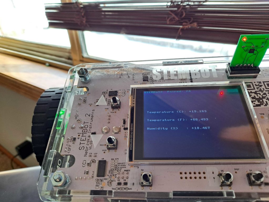
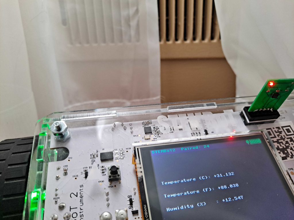
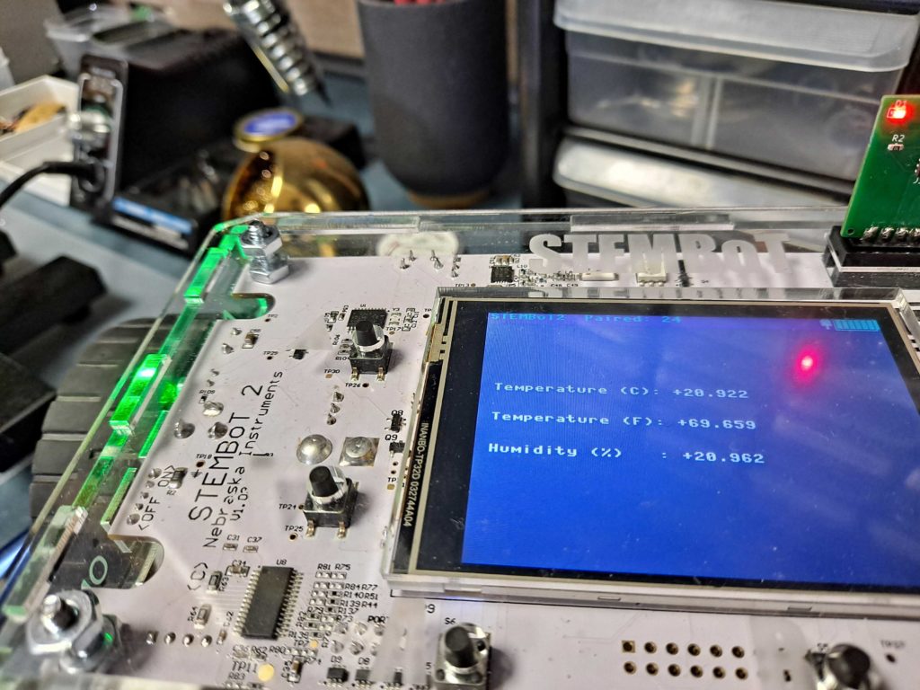
I took my STEMBoT around to see where I could improve insulation throughout my home:

It’s reasonably comfortable in my home office

The area near my basement windows definitely needs improvement

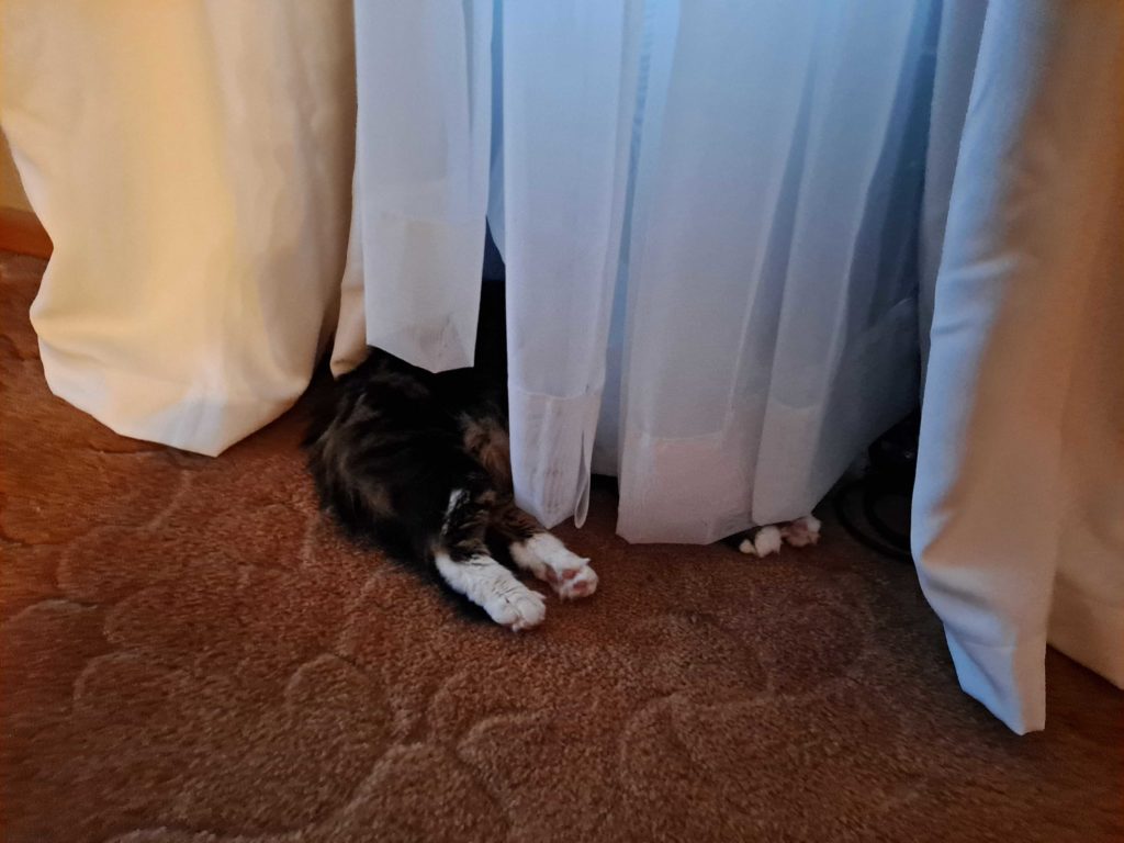
Of course it’s warmest right next to the heating/cooling vent. That must be why my cat loves hanging out there!

Program used: DEMO_PnP_SHT21

PnP Module Used: SHT21 Temperature/Humidity Sensor

New Programming Guides

In anticipation of this year’s Nebraska Robotics Expo, SBI has started working on a series of YouTube videos that explain how to program the STEMBoT. The series will start with the most basic programming features and will work through use of the Plug and Play modules as well as fun applications of the same!

The User’s Manual has been updated to reflect the most current API. In addition, a quick programming reference has been developed and can be found here. The new guide goes over each of the STEMBoT capabilities at a high level for easy use.

Mobile Programming Application!

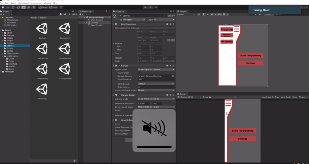
Along with the STEMBoT 2 launch, we hope to deploy a functional version of our drag and drop mobile programming application before the end of the year. 

The STEMBoT Mobile app will enable students and teachers to use drag and drop programming to design their programs that they can wirelessly upload to their STEMBoT 2. 

Likewise, teachers will be able to use the mobile application to share specific programs to go along with their lessons. We are very excited about the potential this app has for greatly improving virtual-learning and at-school learning. It will make lesson setup so much faster and simpler for organizations and their educators! 

In addition, with support from the University of Nebraska’s computer science department capstone team, the mobile application will also have a Simulation component that allows students without a STEMBoT to simulate their code in a really cool 3d environment. Students will get to gain hands-on critical thinking and programming experience, even without a robot! 

On another note, our two engineering interns are learning all about advanced power supply concepts and electronics engineering! 

STEMBoT 2 Launch

Ro-burt is ecstatic to announce the arrival of the STEMBoT 2 educational robot!

STEMBoT 2 kickstarter orders are being fulfilled as of Monday, October 26th, 2020. The STEMBoT 2 package comes with the STEMBoT 2 robot, remote controller, 2 Plug and Play accessories, and a programming cable. Our development team is working hard to complete the drag and drop mobile programming application. Along with this, we are working with the University of Nebraska-Computer Science department to design a 3d simulation that will be part of the mobile application! This will make it so ALL students have access to really neat STEAM based lessons, regardless of whether or not they have the STEMBoT 2 itself.

The SB2 educational robotics platform is becoming a stronger hands-on virtual and in-school learning tool with each week that we continue to improve the platform. We are so very grateful for your support. If you haven’t received your order yet, don’t worry, your order will be on its way shortly.

STEMBoTs Are On the Way!

We are very pleased to announce the brand new STEMBoT 2 educational robotics platform is going to be on the market starting in mid October. SB2 is a major improvement over its predecessor, the SB1. It has a neat programmable 3.5″ LCD screen, brand new User Interface, can hold numerous programs, has a brand new custom remote controller, programmable in python, and will be a fantastic virtual learning tool. Students from kindergarten through college will harness their potential in STEM through numerous programming and hardware challenges.

STEMBoT 2s will be made available for for online purchase shortly. Thank you for your continued support!

The STEMBoT 2 with three Plug and Play Accessories plugged in- a 7 segment display, a thermal/humidity sensor, and a grid of 16 programmable LEDs!